Overview
In this chapter we will describe a method to generate a DAIR neural controller for a complex robot, whose behaviour can be tuned based on a tonic value from an external source. The signal modifying the behaviour will be referred to as the TOC (from TOnic Control ). The TOC signal is intended to originate from outside the DAIR controller, and could potentially stem from a user control panel or any other external deliberative modules which may have been implemented with other mechanisms different to DAIR. What is mandatory is that the TOC signal must at every time step provide a value which represents a desired status, from the outside module, and into the behaviour of the controller.
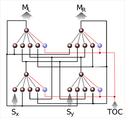
Figure 1: Schematics of a final DAIR controller with TOC signal, for the
control of a robot with two sensors and two actuators.
The method
The procedure begins in the same way as
in the progressive design method described in chapter 6. Firstly, a
staged evolutionary strategy is selected by the designer. Hence the
number of stages N required to evolve the controller is decided, as
well as the modules that will be evolved in each stage. At this point,
the first evolutionary stage is performed in the same way as described
in chapter 6, using the provided f1 fitness function. Once the modules
involved in stage-1 have been evolved and the stage finished, a new
input t is added to all the IHU modules evolved. That new input will be
the input from the TOC signal. The weight connecting this new input to
the inner neurons of the neural network of each IHU is randomly
initialised. The evolutionary process from stage 1 is then resumed, but
using a modified fitness function f1' which adds an additional term
to
the original fitness function, indicating how the controller's
behavior
has to change based on the TOC value. The new fitness function will now
be something different, including the f1 term, and an additional term
based on the behaviour_measure1 value.
During the evolutionary process with f1' , the evaluation of a given controller is performed several times, with different TOC values. The whole process is repeated for all the designed evolutionary stages, by defining at each stage functions fi' fn, and behavior_measurei. The final result is the complete DAIR controller whose behaviour changes depending on the TOC value.
Application to Aibo walking behavior
First stage: single joint oscillation at several speeds
The following video shows the resulting oscillation obtained for joint J1. The oscillation changes its speed along the video when the TOC value changes.
Second stage: two joints oscillating at several speeds
The following video shows the resulting oscillation obtained for joints J1. The oscillation changes its speed along the video when the TOC value changes.